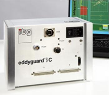

eddyvisor® C Eddy Current Test Instrument Description
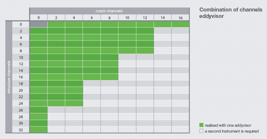
The eddyvisor® distinguishes itself with its high performance modular concept with max. 16 independently working crack detection channels and max. 32 structure test channels all in a very compact design. Additionally, it offers unique features for the realization of sophisticated test tasks using the eddy current technique, combined with the well known ibg test reliability and ease of operation.
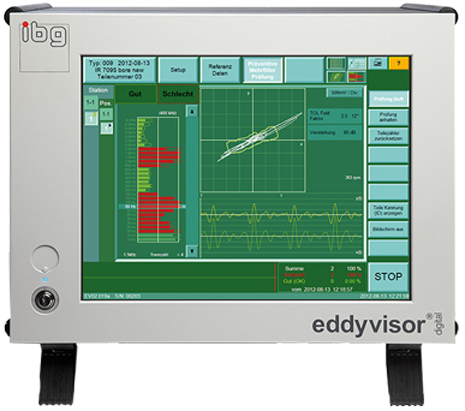
The ergonomic interface enables easy and simple operation via touch screen. All functions and test results are captured at a glance. Digital processing of the measuring signal with unique processors, immediately after the pre-amplifier guarantees the greatest possible stability of test results.
The eddyvisor® eddy current test instrument is based on the long proven ibg system concept. All coils, probes, rotating heads and other system components are standardized worldwide. So eddyvisor® is the solution for new tasks and to upgrade existing production machines to equip them with state of the art eddy current technology.
In the field of crack and grinder burn detection, the need for trained experts to perform the sophisticated and time consuming tasks of manual determination and setting of suitable filter band, phase angle and gain is eliminated by ibg’s exclusively developed Preventive Multi-Filter Technology (PMFT), which automatically creates tolerance zones by simply scanning good parts. This quantum leap in eddy current technology, unique to ibg worldwide, establishes a new standard for quality in crack and grinder burn detection by the eddy current method.
During material data recording (calibration) with PMFT, surface areas of several good parts are scanned. The good surface eddy current “noise“ is recorded simultaneously in each of 30 band pass filters. Tolerance zones, enveloping 360 degrees, are automatically created within each filter band, capturing the allowable eddy current “noise“ from good parts. Good part noise signals result from allowable variations in surface roughness and material properties. Thus, the thirty tolerance zones store the part specific fingerprint of the good parts. Edge effects, hardness profile run out, eccentricity, etc. of the good parts are calibrated during material data recording. Thus, pseudo rejected parts are reduced considerably without losing visibility to real flaws in parts.
The unique “good-part-only-concept“ enables setup within a few minutes. Simply scan and record an adequate number of good parts. Tolerance zones within each of the 30 PMFT filter bands are automatically generated capturing the allowable noise from the good parts to form good part finger prints in each of the 30 PMFT filter bands. After material data recording, one key press switches to Preventive MultiFilter Test, and the test can start. Done! Faster starting yet more reliable eddy current testing is not possible.
Crack and Grinder Burn Detection:
Efforts to reduce content of valuable raw materials and of energy bring reduced cross sections in high volume components in the fields of mechanical engineering and automobile components. The resulting reduced cross sections and stricter material properties requirements have incentivized manufacturers to guarantee correct structure and crack and grinder burn free condition by increased nondestructive testing.
The eddy current test method can be applied for all materials with electrical conductivity or magnetic conductivity (permeability). This includes all metallic materials. The eddy current crack and grinder burn test can be adapted to many test tasks by selecting the suitable crack detection probe and transmitter frequency. As a matter of principle, mainly surface open or flaws close to surface and pores are detected.
The test resolution and effective scan width of a crack detection probe is dependent on core size and type (between 0.5 and 5.0 mm). When testing, a relative movement of probe to surface of test part is always required. In order to test rotationally symmetrical parts for cracks, either the test part is rotated and the probe stands still or the test part stands still and the probe is rotated around the part by means of a rotating head. If more than one line shall be tested additional feed forward is needed. Thus complete surfaces can be scanned. More complicated surfaces require more complicated mechanical handling systems. Our own special machine manufacturing group is always pleased to work with you to design and build an eddy current test system for your 100% testing.
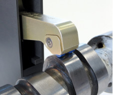 | Crack detection probe box for contacting testing on eccentric parts like camshaft lobes for cracks and grinder burn; large diameter range is covered; up to 300 rpm (depending on part geometry), ceramic supports for long life-time. Solutions for structure test on camshafts on request. |
In the past, the eddy current crack test would be set to optimally detect an artificially generated (EDM) defect master. But artificial defect masters show different eddy current behavior (i.e., phase shift, etc.) than natural defects. Thus, natural defects could go undetected. Now the ibg technique with its eddyvisor® instrument family walks on new paths. Thanks to the Preventive Multi-Filter Technology and Simultaneous Harmonic Analysis, the instrument is not set to an artificial defect anymore but to the eddy current pattern of "healthy" surfaces of several OK parts. Automatically, 30 tolerance zones over the entire spectrum of filter bands are formed which in fact picture the "healthy" surfaces in the test instrument. As soon as one of these tolerance zones are exceeded by the eddy current signal a NOK signal is triggered, no matter if caused by an artificial or by a natural defect.
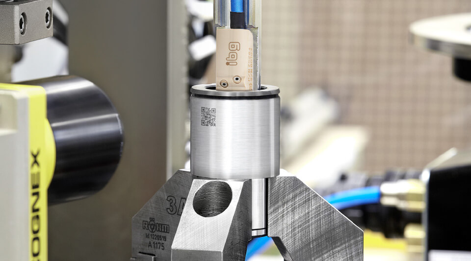 | Steering nut in an automatic ibg test system. Detection of cracks and grinder burn defects on the race inside. With camera inspection system to capture part type specific QR-code. |
For proof of test sensitivity, an artificial defect is put into an OK part by EDM processes. This defect must be 100% detected by the instrument for validation of the method and of the test system. The limit defect of your application is determined beforehand in our lab during a feasibility study. It results in definition of direction and dimension of the smallest reproducible defect that must be 100 % detected without or without significant pseudo rejects.
The well-known note “surface to be free from cracks” on drawings suggests a wish for perfection of the part ibg lathe for lab tests, feasibility studies and small series in crack detection with eddyvisor®. Speed max. 850 rpm, chuck up to 68 mm diameter, with trigger sensor, flexible probe movement. to be produced. However, there are physical limits of the eddy current crack detection relative to that wish. We have committed ourselves to move these limits further in the direction of smaller, detectable “discontinuities” without increases in pseudo rejects and under production conditions. The exploitable sensitivity of the eddy current crack test depends on several parameter:
- Surface roughness - detection of small defects is better the smoother the surface is. The limit is at defect depth equal to 5 times roughness depth, but not less than 50 µm.
- Material - use of differential probes generally suppresses noise inherent to different materials. But the material tested is a factor. For example, the detection limit for lamellar cast iron can increase to approx. 150 µm due to carbon needles in this material.
- Distance probe to surface - increasing probe distance reduces sensitivity, while decreasing probe distance enhance sensitivity to surface roughness and eccentricity of the test part. A good compromise for most applications is the ibg standard probe distance of 0.7 mm.
- Direction of defects - the direction of a defect relative to the probe trace direction also influences the test sensitivity. This can be influenced by choosing the suitable ibg probe system.
ibg mainly applies differential probes for crack detection. The differential principle reduces the very large receiver signal almost to zero by use of two compensating counter rotating receiver windings. This enables very high amplification of very small signals from flaws without overloading the input of the test instrument. Furthermore, ibg places high standards for precision for its own probe manufacturing, further enabling higher amplifications. On the noise side, ibg instruments employ extremely low noise signal processing, earliest possible digitalization and smart signal processes. Thus, ibg is able to combine very high flaw signal amplification with very low noise signal processing allowing larger distances between test probe and test surface without loss of test sensitivity. The advantage realized is that ibg test probes can be held 0.7 mm off of tested surfaces without sacrifice of test sensitivity and test resolution. The small flaws are detected. Other eddy current test equipment manufacturers only guarantee similar sensitivity with 0.2 – 0.3 mm probe distance. But probes so close see more good part noise, and there are more pseudo rejects of good parts. In general, differential probes are highly sensitive for local surface defects. These eddy current probes are also relatively immune to variations in test part structure such as different batches, allowable heat teat variations, etc. These characteristics are important for avoidance of pseudo rejects when doing 100% zero defect testing.
Grinder Burn Detection
As per ISO 14104, grinder burn is a local overheating of surfaces. Heat impact during the grinding process was too much and effected localized annealing or, if heat impact was still stronger, there can be re-hardening zones. Depending on part surface quality and geometric influences, the ibg PMFT detects grinder burn with detection beginning at the level of mere change in residual stress or beginning of annealing zones in the microstructure.
A method applied by ibg to produce reference samples for grinder burn detection is laser burn: heat, defined and locally applied to the surface of the test part. Thus, producing defined artificial defects of different intensity in metallic parts which show analogue features like real damage. They can widely be produced and reproduced at defined spots according to requirements (kind and depth of structure change, spacial dimension) and they serve as master part for validation of automatic test machine as well as for determination of sensitivity of a test systems.
Features crack and grinder burn detection:
- Probes
A selection of probes for crack detection is available which vary in trace width, sensitivity and shape. custom eddy current probes for special applications are designed and manufactured in house. Compact and highly precise ibg rotating heads eddyscan® H and eddyscan® F are available, in many cases installed for optimization of cycle time. They work together with the test instrument eddyvisor®. Cable break monitoring offers high security in continuous operation. - Probe distance
ibg probes are by default manufactured for a large probe/part distance of 0.7 mm. Thus, demands on part exactness and test mechanic are relaxed considerably. - Lift-off compensation
If a part is very eccentric, the distance of probe to test part may be additionally balanced electronically by use of the optional lift-off compensation. Special lift-off compensation probes are supplied for this function. - Suspend
The suspend function blanks out areas not to be tested like holes or similar. - Display
Display of test results as bargraph, xy-diagram with tolerance zones and x(t) and y(t) or three-dimensional C-scan display can be selected. The C-scan (or waterfall diagram) is a rotationally synchronized display of test signal from part circumference enabling local allocation of defects on the surface. - Frequency range
The carrier frequency is selectable within a range of 3 kHz to 10 MHz in 21 steps. The filter frequencies of the 30 band pass filters distribute in the range of 6 Hz to 20 kHz. - Trigger of test
Manually on the instrument, via PLC or by optional start button.
General:
- Ergonomic design
All functions and test results including for complex systems are clearly arranged to be viewed at a glance. This enables correct and easy operation even for inexperienced operators. - Stations and Locations
The eddyvisor® offers a unique station and location concept for solution of complex applications. Maximum eight stations can be defined which may include up to 32 locations. All test locations of one station belong to the same part and are summed up in a station result. This result can be taken for sorting. The part must be tested at all locations of that station in order to get a valid station result. Stations are independent from other stations. Different stations can take different operating conditions. For exapmle, one station can be testing parts, and another station can be recording new calibration data or being adjusted. In addition, each location has its own set of reference data and tolerance zones. For crack detection, for instance, it is possible to define different areas of a test part (faces, radii, undercuts etc.) and to test each of them with different settings switchable via PLC on the fly. So each area of a test part, including areas with high basic noise (e.g. radii) or with very low basic noise (e.g. high precision machined or super finished surfaces) can be tested with the setting optimised for that area without disturbing testing of the other areas. - View of test part
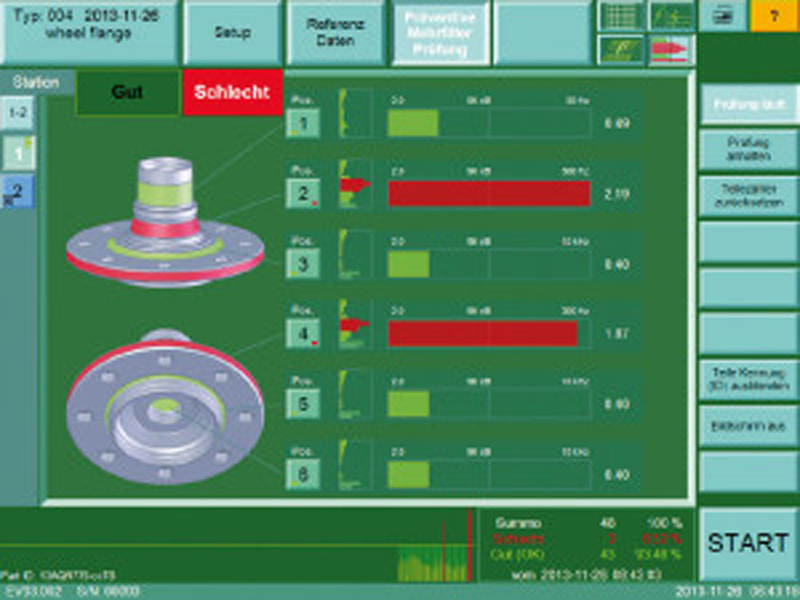
At stations with at least two and maximum 22 locations a picture of the test part created by customer may be included. The test result of the single locations of the station is visualised by coloration of the test part picture. A huge help for the operator especially in test system with complex setup. These test part pictures can be displayed in the survey of all stations as well (however, w/o coloration of result). - Part types
Maximum 100 part types (at more than eight locations max. 50) in crack detection and max. 250 part types in structure test with all settings and reference data can be stored in the device memory and switched over manually or via PLC for automated processes. - Part ID
Test data for individual parts can be allocated to the part. The eddyvisor® can be informed before the test of an alphanumeric serial number from a PLC or another system (QR-code reader or similar). This identity is connected with the related test data, stored in the eddyvisor® and additionally written via the eddyLogger Software or as Q-DAS compliant set of data. Indispensable for back tracing individual parts. - History of reference parts
The histogram displays the test results of all reference parts at a glance. When after recording of reference parts and afterwards crosschecking in the laboratory it is determined that a part is still not good, it can be removed from the reference parts with one keystroke. - History of sorting parts
The multi-colored histogram displays the test results of up to 1000 sorted parts and additionally the last 100 bad parts, so they can be observed at a glance and evaluated later. Test results of questionable rejected parts can be recorded as tentative reference parts and later destructively cross checked in the laboratory. If such questionable rejected parts are later found to be good, they can be added to the reference parts with one keystroke. Pseudo rejects can be diminished. - AQDEF quality data export Q-DAS standard compliant (option)
Test data are transferred after termination of each test part via Ethernet to a protocol computer where the free eddyLogger Q-DAS software receives the data and provides them AQDEF compliantly to the QSSTAT interface. The software allows the user an individual configuration. The following options are available per test station: selection of data to be stored; storage with K-field or abbreviated separator spelling; memory format as DFD/DFX or DFQ files; free choice of amount of test parts to be stored per file. The eddyLogger software may record and administrate parallel the test data of several ibg instruments within one Ethernet network so that one acquisition computer is able to supervise several eddyvisor® and/or eddyliner® instruments. - Data storage in general
Test results, part types and instrument settings are stored internally on a tough flash-memory and externally via USB stick. Test results may be additionally logged via network. A ring buffer logfile records all internal failures and allows fast debugging for service.
- Automation without PLC
Direct control of sorting devices, paint marking systems or indicating lamps is possible with the integrated 24 V DC (2.5 A) power supply, together with the autostart function providing a low cost solution for small automated systems without an additional PLC. - Counter preset
The function “box counter” monitors the filling height of containers to avoid overfilling. Testing is paused automatically as soon as a preset value of tested parts is reached. The operator changes the containers and reset the counter, testing starts again automatically. - Remote control
The eddyvisor® is remote controlled by each network PC via VNC viewer software. - Access protection
The instrument offers a multi-level access authorisation concept that operates by keyswitch. - Help function
The user always has access to a context sensitive help function on the device screen which often renders a look into the manual unnecessary. - Languages
Included are: German, English, Spanish, French, Italian, Czech, Polish, Portuguese, Chinese, Hungarian, Japanese, Korean and Russian. Other languages as option. - Screen
Tough 15” TFT touch screen, color display, resolution 1024 x 768 pixel, operable with gloves