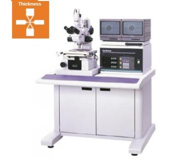
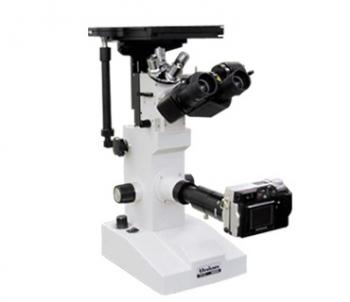
Overview
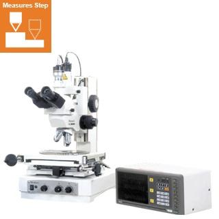
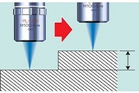
HISOMET realizes non-contact, high-precision height/depth measurement with simple operation, observing the surface of measuring point. HISOMET-II is a non-contact depth measuring microscope that has been designed based on an optical type focal point detection system. Adopting precise focus indicator, it's possible to measure height, depth, steps, etc. with observing the surface of measuring point, by simply coinciding the halves of an index graticule. Since there are no concern for physical damages such as distortion, blow or nicks to a specimen because of non-contact system, HISOMET is optimum for measuring electronic components such as ICs or high-precision processing parts.
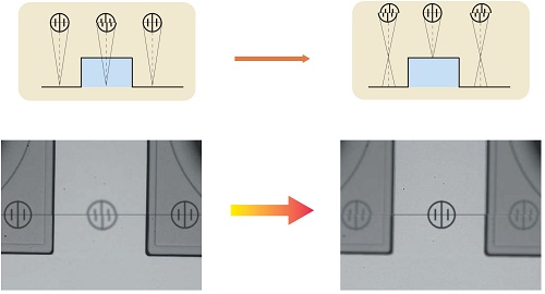
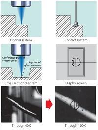
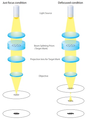
This microscope system offers a precise focus indicator consisting of an index graticule (Target Mark) and a beam splitting prism built into reflecting illumination optical system of microscope. And it has been designed based on the optical principle that at just focus status, of which the upper and lower halves coincide, can be observed above the focused image of a specimen, and that when defocused even slightly, the index line is split into two lines in the upper and lower halves of the graticule
 |
|
Measurement Method
Advantages:
- As a focal point is detected under the non-contact optical method, measurements can be taken without being affected
by physical damages to a specimen such as distortion, blow or nicks, etc.
- Since the precise focus indicator based on the “split-target” method has been adopted, highly-accurate depth
measurements can be taken simply by coinciding the two halves of the graticule.
- As the operation is so simple, this is the most suitable measuring microscope system for various kinds of applications.
- While observing minute surface condition of a point of measurement, the positional relation between a reference point
of measurement and a point of measurement can be confirmed, and measurements can be also taken in the same field
of view.
- Measurement accuracy can be improved through the use of high magnification objective lenses.
- Either Black-stripe or White-stripe Target Mark can be chosen as per a condition of specimen surface. Since three kinds
of Target Mark status (black-stripe, while-stripe and nothing) can be selected by a lever, the photographs can be taken
without the Target Mark if necessary.
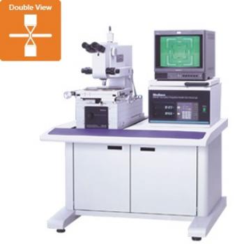
- Various models can be configured by the combination of different equipment such as viewing head, measuring stage
and other optional items, depending on applications of respective users. (Refer to System Diagram)
- In case of observing transparent, mirror or pearskin finish surfaces with a laser system, focus errors are apt to occur due
to diffuse reflection. While, Target Mark can be projected onto such surfaces in case of our optical system, step heights
of such specimen surfaces can be measured
Specification:
| Microscope Stand & Bracket | Travel | Coarse Adjustable | 140mm |
| Fine Adjustable | 25mm or 10mm | ||
| Height of specimen | 150mm | ||
| Illuminator | Reflecting | Illumination with Index Graticule 3W White LED | |
| Transmitted* (Option) | Telecentric Illumination 3W White LED | ||
| Z-axis measuring | 1μm, 0.5μm and 0.1μm(option)reading / 25mm or 10mm travel | ||
| Z-axis measuring Accuracy | 3σ= 1μm (using 40× Objective) | ||
| Viewing Head | Erected Trinocular | Binocular with TV C-mount Tube | |
| Objectives | PLM, PLLWDM, SPLM series | 3X, 5X, 10X, 20X, 40X, 50X, 100X | |
| Eyepiece | NWF10X | Field Number φ16mm with Offset Hair Line Crossed Reticle | |
| Measuring Stage | Travel (X-Y) | 50×50・100×50・100×100・150×150・200×100・200×200・300×150・300×300mm | |
| Measuring Accuracy | X:(4+0.02L)μm, Y:(4+0.02L)μm, L:Travel Distance (mm) | ||
| Options | CCD Camera, Monitor, Measurement Software | ||
Application:
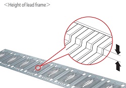 | 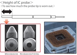 |
| Height of lead frame | Height of IC probe |
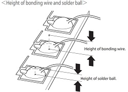 | 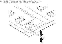 |
| Height of solder ball | Terminal steps on multi-layer PC boards |
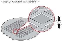 | 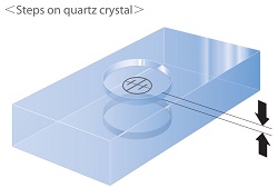 |
Step on the wafers such as Si and GaAs | Steps on quartz crystal |
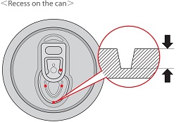 | 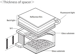 |
Recess on the can | Thickness of spacer |

